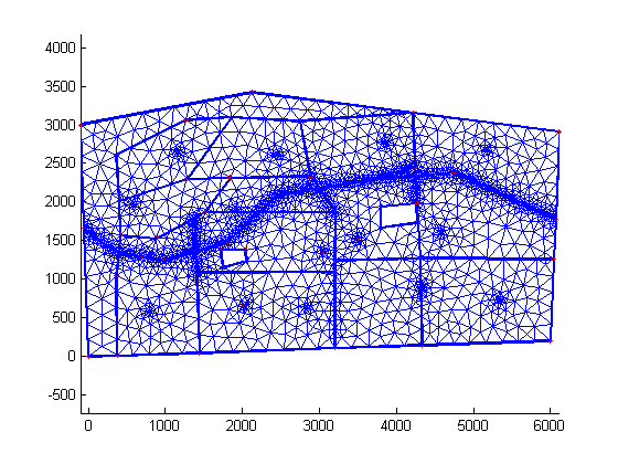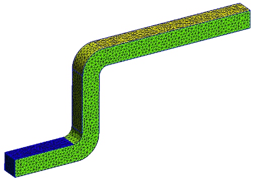
The gmsh input is shown below and this is the first text to put into the structured_ex.geo file. To create the square, four points are speficied and these are connected by four lines. For this tutorial, a square shape is first created. The shape to be meshed will be created by specifying points and then connecting these points with lines. screenshot ( "subdomains_unstructured.The first step in creating a mesh is to create some shape that will be meshed. I continue by creating a volume mesh using gmsh derived from the surface mesh. You can load this file into the gmsh GUI and press 2 D under Mesh to create a mesh like this: (In my installation 4.8.4, keyboard 2 was the shortcut key to this 2 D meshing.), If you want the surface elements to appear colored, select the Mesh panel in Tools > Options and select the Mesh panel and select the 2 D element You may need to check Faces. add_mesh ( grid_uh, show_edges = True ) if not pyvista. The tutorials are also a great tool to progress with gmsh, I use them a lot. UnstructuredGrid ( * create_vtk_mesh ( V )) grid_uh. This document is a tutorial on the GMSH mesh generator. This tutorial shows all the steps involved in the creation of a simple We start by launching Gmsh, then we click on ‘Elementary’ to create new. Plotter ( window_size =, shape = ( 1, 2 )) p. This provides a short step by step guide to meshing an aerofoil using the gmsh package. set_active_scalars ( "Marker" ) p = pyvista. UnstructuredGrid ( topology, cell_types, x ) num_local_cells = mesh. solve () # As the dolfinx.MeshTag contains a value for every cell in the # geometry, we can attach it directly to the grid topology, cell_types, x = create_vtk_mesh ( mesh, mesh. incorporation of structural information, usage of a complete electrode model.

When the scientific task requires a complex finite-element discretization (i.e.
#CREATE MESH TUTORIAL GMSH GENERATOR#
Problem = LinearProblem ( a, L, bcs = bcs, petsc_options = ) uh = problem. Create the mesh in Gmsh, a 3D finite element mesh generator with parametric input and advanced visualization capabilities, and convert it to GIMLi for subsequent modelling and inversion. Then, from the left hand bar, select Modules > Mesh > 2D and this should produce a triangular and fairly homogeneous surfacic mesh. You may also choose to decrease your element size to obtain a courser or finer mesh.

JIT Parameters and visualization using PandasĮrror control: Computing convergence rates Open this file in Gmsh, and select Tools > Options and set your 2D algorithm to MeshAdapt. Setting multiple Dirichlet, Neumann, and Robin conditions The geometry to be created and meshed with a structured mesh Create a new file Add the text shown above to your input text file, save, and then click Reload.
#CREATE MESH TUTORIAL GMSH HOW TO#
COMMSELF, cells, x, ufldomain ) As the meshes can contain markers for the cells or any sub entity, the next snippets show how to extract this info to GMSH into dolfinx.MeshTags. Test problem 2: Flow past a cylinder (DFG 2D-3 benchmark)Ĭombining Dirichlet and Neumann conditionsĭefining subdomains for different materials from sh import createmesh from mpi4py import MPI mesh createmesh (MPI.

Test problem 1: Channel flow (Poiseuille flow) After selecting your mesh and following the on. Weak imposition of Dirichlet conditions for the Poisson problem I opened my file with File -> Merge and used Geometry -> Elementary entities -> Add -> Volume.


 0 kommentar(er)
